Sunday, May 31, 2015

Testing Repaired Quadro FX4600 in a Dell Precision 690

A while back I fixed up a defective graphics card from Ebay. I had to wait a couple weeks for a Molex connector adapter to arrive before I could give the card a test run. The adapter arrived today.


All in all I'm really happy with this setup. I regard the Dell Precision 690 platform as a somewhat well kept secret for super low-budget, second-hand, high performance workstation configurations. This is what I put together for a project  I'm involved with:
  • Tower + 1.6GHz Dual Core Xeon + 500GB HD + 4GB RAM: $90
  • Upgrade to 3GHz Dual Core Xeon: $5
  • Upgrade to 12GB RAM: $20
  • Upgrade to Quadro FX4600 Graphics Card: $20
  • Adding a 64GB SSD: $30
Total:  $165

That is a pretty neat machine for UNDER $200. And get this: it has a dual socket motherboard that can power two quad core CPUs, accepts up to 32GB of RAM, and 8 SATA drives. With a budget of just $400 this machine could be completely tricked out and would make a fantastic low-budget video and graphics editing station. The tower itself is built like a tank, too. So, if you're looking for DIY processing power on the cheap, I highly recommend you check Ebay for used Dell Precision 690s and compatible hardware upgrades. 

Wednesday, May 20, 2015

Preparing to experiment with RAM based Neural Networks

I got my hands on some old 30-pin RAM modules. One of the memory chips on each module appears to be arranged as 1024x1bit, meaning 10 address lines, 1bit of memory at each address. As far as I understand, this type of memory configuration is what is used for RAM based neural networks.

This article on teco.edu provides some insight into the concept of RAM based, logical neural networks: http://www.teco.edu/~albrecht/neuro/html/node23.html

At this point I'm still working on getting to where I can use the chips on a breadboard. Removing the ICs from the modules was not difficult, but preparing a piece of strip board to accept the ram chip was very time consuming.

DIY SOIC24 adapter for RAM based Neural Network

After completing just one DIY adapter, I decided to just spend a few bucks and get some SOIC24 adapter kits from Ebay.

Commercial SOIC24 adapter for RAM based Neural Network

The actual IC pin arrangement is longer than SOIC24, even though the package only has 20 pins.

Assembled SOIC24 adapter with 20-pin RAM chip

I had to bend the pins to match the solder pads and added a 100nF capacitor.

Now I just have a few more memory chips to solder and datasheets to study. Of course, before I get to actually design a simple, RAM based neural network, I have to first master interfacing with the chip, reading and writing data, refresh cycles etc. Fun stuff!

DIY Magnetic Stirrer Video


As mentioned in a previous post, a beer brewing friend asked me to build a magnetic stirrer for his yeast cultivation setup. This is the finished device. The guts are made from a 80mm 12V computer fan with chopped off blades, a couple strip boards, some neodymium magnets, and PVC plumbing pieces. I used an adjustable linear voltage regulator (LM317) to control the speed.

12V Fan Speed Regulator Circuit
Fan Motor Speed Control Circuit Diagram


DIY Magnetic Stirrer Exterior
Magnetic Stirrer Exterior

DIY Magnetic Stirrer Interior
Magnetic Stirrer Interior

Fan Motor Speed Control Circuit

Sunday, May 10, 2015

DIY Magnetic Stirrer Progress

A beer brewing friend asked me to build a magnetic stirrer for his yeast cultivation setup.

DIY Magnetic Mixer

The stirrer I'm building uses the core of a 80mm brushless DC computer fan with its blades cut off, sanded, balanced, and mounted on a piece of strip board. Some carefully cut and sanded 1" PVC coupling and pipe hold a neodymium magnet rod in place. There is transparent plastic shielding around the motor to prevent wiring from getting caught in it during operation.

The speed control of the motor is realized with an adjustable LM317 linear voltage regulator. This is the circuit I made.

12V Computer Fan Motor Speed Control Circuit
In this circuit the maximum voltage at the fan motor is only about 10V, but that should still be plenty fast for a magnetic stirrer.

Saturday, May 9, 2015

Quadro FX4600 Repair & Cleanup

Nvidia Quadro FX4600 with heatsink removed

Bought a used FX4600 for cheap on Ebay.


Nvidia Quadro FX4600 with damaged capacitor

After unpacking I noticed a sheered-off capacitor.


Nvidia Quadro FX4600 with repaired capacitor

I soldered the capacitor back in place and cleaned up the board.


Nvidia Quadro FX4600 with dull heatsink

Not shiny enough. 


Nvidia Quadro FX4600 with polished heatsink

Better.

I finished the job the next evening after work, but was too tired to take pictures during it. Thermal paste was applied where needed and the heat sink mounted back onto the board. 

When I went to install the card I realized I didn't have a Molex-to-Graphicscard adapter to power the beast. We'll have to wait until the adapter arrives in the mail to find out if this old workhorse still has some life left in it.


Thursday, May 7, 2015

Artificial Neural Networks on Arduino

I want to share this fantastic write-up by an anonymous editor and programmer that I found today:


I can see pieces of this finding their way into the Tamaduino project, or at least leading to some fun experiments. It immediately had me wondering how easily the provided code could be adapted to take advantage of external memory as to not be restricted by the ATmega328's 2k SRAM.

New Tamaduino Page, Side Gigs

As you can see at the top of the blog, I added a Tamaduino page. The page is an attempt to provide more context for the project and details about the different resources that form the foundation of this project.

In other news, I'm still waiting for the new circuits from browndoggadets.com.

In the mean time I'm keeping my self busy with some side projects:
  • building a magnetic stirrer for my friends yeast-cultivation  
  • constructing a digital neuron from an old 10x1bit DRAM chip

I'll add some pictures as soon as I get to it!

Sunday, May 3, 2015

It wasn't me, I swear!

I was pretty excited when I received the replacement charge controller in the mail and was looking forward to build the Energy Brain test circuit. Just to be sure that this charge controller would work, I wired up a charged Li-Ion cell and checked the output of the DC/DC converter.

0V on the DC/DC output. The exact same problematic behavior as with the first circuit, only this time I had not messed with it at all. After some further investigation it seemed like the MOSFETs were not connecting the cell to the rest of the circuit. 

It is not clear to me if the over/discharge protection IC is failing at engaging the MOSFETs, or if the MOSFETs used for this circuit don't have the right specifications. Maybe there is some kind of gate capacitance that builds up and needs to be discharged prior to initialization of the protection circuit.

The circuit will work if either the MOSFET gates are briefly connected to B-, or if the P-/P+ terminals are connected to a solid 5V DC source, like a USB outlet.

I called browndoggadgets.com and they were able to reproduce the same (mis)behavior and graciously offered to replace my purchases with substitute circuits that should get the job done.  

That means more cool stuff coming in the mail for me this week!

Wednesday, April 29, 2015

The Cost of doing Business... erm, Carelessness

After testing different ways of interfacing a uC with the Li-Ion charge control circuit, I accidentally put the over/discharge protection circuit out of commission when I connected the B- and the V- GND nets. Best I can tell is that the GTT8205S MOSFET got damaged and is no longer reliably connecting the battery to the rest of the circuit. Oh well. I already ordered a replacement.

Here's a circuit diagram for a test-version of the Energy Brain. I use an optocoupler to control the charging of the super-capacitor so that in later versions of the device an external uC on a separate power net can trigger a recharge of the capacitor.


Until a replacement for the fallen soldier arrives, I'll dink around with some other things. I've been reading up on artificial-neural-networks (ANNs) and that has been giving me some ideas, to say the least.

Saturday, April 25, 2015

Tools of the Trade

I use an old Arduino Duemilanove as my In-System-Programmer to flash bootloaders and software onto ATtiny and ATmega uCs.  There are a number of decent guides out there on how to do that:


The greatest source of frustration and errors for me has been flimsy breadboard setups, especially if I'm repeatedly programming different chips during a project.

I've since built a couple of custom mini-shields to make the process as painless as possible.

Meet the Freeloader and the Privateer:


The two mini-shields allow me to switch between different size capacitors for the RESET and 5V pin on the Duemilanove. I've found that the required capacitance for error-free flashing changes depending on the frequency and type of oscillator I am fusing the chip for.

A Brain in a Brain

The circuit discussed in my last two posts already has some intelligence of its own. The TP4057 charge control IC switches between constant current and voltage mode as the lithium cell increases in charge, and the DW01AM over- and discharge protection IC disconnects the battery's negative terminal from the rest of the circuit in the event that its voltage drops below 2V, or if the charge voltage rises over 4.3V.

As part of the Energy Brain I want the ATtiny uC to monitor the Li-Ion cell and the super-capacitor voltage. When either drops below a certain level, the ATtiny communicates on an interrupt line with the uC in the Memory & Learning Brain and lets it know what's up. The Memory & Learning Brain can then decide what to do with that information; to initiate a recharge of the super-capacitor, to communicate a request for solar charge to the outside world, to alter sensing and communication behavior in ways that conserve energy, or to send other Brains into sleep mode.

What I'm trying to mimic here is the connection between the biological gut and brain; the involuntary sensation of hunger or exhaustion, and the intentional decision to eat, sleep, or forage for food.


HP-0014B PRO Charge Controller Circuit Diagram

I spent some time mapping the Li-Ion charging circuit I purchased. As far as I can tell the circuit is a combination of the reference design for each of the integrated circuits - U2, U3, and U4 - and an RC filter. My guess is that the RC filter is supposed to keep the noise from the DC/DC converter from interfering with the current monitoring of the lithium cell charging IC.

The next step is to evaluate the best way to interface an ATtiny85 to monitor and control the circuit.

HP-0014B PRO Charge Controller Circuit Diagram


HP-0014B PRO Charge Controller Circuit Board


Datasheets:

Wednesday, April 22, 2015

Hardware for the Energy Brain

Most of these components were left over from other projects:


My experience building charge controllers and switching power supplies is limited. To save time I ordered this little circuit from browndoggadgets.com:


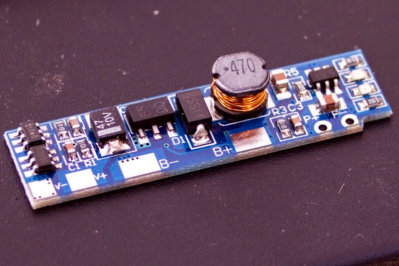
This 3.7V Li-Ion charge control circuit accepts 5V Vin and has an integrated 5V boost supply that feeds off the battery. My hope is to modify the circuit board so that the ATtiny85 uC can turn the 5V boost supply on and off as needed.

Tuesday, April 21, 2015

Tamaduino: Energy and Stamina

This might seem a little unconventional, but rather than having the Tamaduino's hardware hooked up to a steady power supply, I want to introduce the concept of stamina. I'm thinking of achieving that by using a 1F super-capacitor as primary power source. The capacitor will deplete much more quickly than a battery, but slow enough to allow the Tamaduino to do stuff. 


Depending on the amount of charge stored in the capacitor, the Tamaduino's interactive abilities would change. When the charge drops below a certain level, the Tamaduino will have to rest while the Energy Brain activates a boost circuit and recharges the super-capacitor from a Li-Ion battery. If the charge in the Li-Ion battery drops below a certain level, the Tamaduino will start making an effort to motivate forces in the environment to move the Tamaduino to a location where its solar panel can recharge the Li-Ion battery. Simultaneously it would start changing its overall behavior to conserve as much energy as possible until it has eaten a sufficient amount of photons.

In some way I'm trying to mimic a biological energy metabolism. Humans ingest food and store the energy in different mediums. Some of them are accessible super quickly, like ATP, some of them require metabolizing, but are fast acting, like sugar, and some mediums, like fat, are very energy dense but take much more time and effort to be converted into biologically available energy. 

In the Tamaduino's energy metabolism, sunlight would be the food; the Li-Ion battery would be the fat; the super-capacitor would be the glucose; and the distributed electrolyte- and ceramic capacitors would be like ATP. The comparison might be a little off, but I hope my biology metaphors make sense.

Provisional Block Diagram

In my block diagram I'm using the metaphor of different "brains" to identify different subsystems of the Tamaduino. The human brain has parts that are older and more basic, like the brain stem and the cerebellum, and parts that are more recent and complex, such as the frontal lobes. 

Looking at my diagram here, I'd have to say that the "Energy Brain" is the place to start this project. The biological analog of the Energy Brain would be the brain stem. It is responsible for the basic metabolic processes of the host. I'll be publishing a rough draft of the Tamaduino's energy system sometime soon. It's gonna be weird.


Outline of the Tamaduino Project

As the portmanteau suggests, I'm setting out to create a Tamagotchi inspired, Arduino powered device. I'm going to lay out what I have in mind so far to help me conclude the next steps more clearly.

Features:
  • senses sound, light, temperature, vibration/movement, being handled
  • responds to environment with light, sound, vibration, other actuators
  • rechargeable battery and a solar panel
  • AI like software that interacts with its environment to optimize care-taking 

Design Goals:
  • create a device with a survival instinct
  • abstract bio-mimicry throughout the device
  • bottom-up design approach
  • AI being shaped by and engaging in operand conditioning

Frankly, I have no idea what I'm doing and I'm in way over my head. But since I don't care, here's my preliminary TODO list to help guide me through the next few steps:
  1. Create provisional block diagram
  2. Draft a preliminary design for the most fundamental block
  3. Source the necessary hardware
  4. Build, test, improve the block
  5. Modify provisional block diagram
  6. Draft preliminary design for the next most fundamental block
  7. Repeat steps 3 to 6 until project complete

¯\_(ツ)_/¯